- Catalogs
- AeroConversions
- AeroVee Turbo
AeroVee Turbo

AeroVee Turbo
The document provides retrofit instructions for the AeroVee 2.1 Turbo, focusing on turbo kits for pre-assembled AeroVee 2.1 engines. It includes guidelines, specifications, and procedures for installation and maintenance.
Important Information
The AeroVee engine kit is sold "as is" without warranty. Engine monitoring instruments are crucial, and the engine is not approved for certified aircraft.
Specifications
- Weights and Dimensions: 185 lbs without oil and exhaust; dimensions are 30.25” length, 30” width, and 20.0625” height.
- Power and Displacement: 100 HP at 3400 RPM, 2180cc displacement, compression ratios of 7:1 or 8:1.
- Ignition System: "Wasted spark" ignition system with specific spark plug and timing requirements.
- Operating Limitations: Includes idle, cruise, and maximum RPMs, oil temperature, and pressure limits.
Assembly and Service Resources
Resources include the AeroConversions website for service bulletins and tech support via email. Keeping packing lists for maintenance and repair parts is emphasized.
Installation Procedures
Detailed instructions cover dual oil pump installation, valve adjustment, oil cooler installation, exhaust manifold installation, and turbo installation, with step-by-step guidance.
Maintenance
Regular maintenance is crucial for performance and longevity, with procedures for start-up, break-in, and ongoing maintenance outlined.
Conclusion
The manual is a comprehensive guide for the AeroVee 2.1 Turbo engine assembly and operation. Feedback for improvements and staying updated with service bulletins is encouraged.
Safety Precautions
Ensure a well-ventilated workspace, wear protective gear, and avoid using compressed air for cleaning parts. Keep flammable liquids away from ignition sources.
Preparation and Tools
Read and understand instructions thoroughly before starting. Ensure all necessary tools and parts are available.
Cleaning and Inspection
Clean parts with mineral spirits and lubricate as needed. Inspect engine cases and cylinder heads for metal chips.
Assembly Guidelines
Avoid forcing parts into position and using concentrated heat. Refer to the packing list for correct part numbers.
Engine Preparation
For retrofit, disconnect the battery, turn off the fuel shut-off valve, drain oil, and remove specific components. Replace Nikasil cylinders with steel ones if applicable.
Valve Adjustment
Adjust intake and exhaust valves to specified clearances using feeler gauges.
Oil Temperature Plate
Drill and tap the oil temperature plate for sender installation if required.
Mini Sump Installation
Install the mini sump and ensure the reusable filter is cleaned with each oil change.
Oil Cooler Installation
Install the top-mounted oil cooler and ensure proper seal placement.
Exhaust Manifold and Turbo Installation
Install the turbo exhaust manifold and components following detailed instructions.
Turbo Clocking and Installation
The turbo is pre-clocked for proper positioning. Contact AeroConversions if incorrect.
Turbo Installation Procedure
Includes attaching the Turbo Support Bracket, positioning the Turbo Body, and securing components.
Exhaust Installation
Install the Turbo Exhaust Bottom Tube and wrap the exhaust.
Oil Cooler Fence Baffle
Install the Upper Oil Cooler Baffle if not previously fitted.
Intake Manifold Installation
Assemble using silicone couplers and elbows.
Manifold Pressure Line Installation
Install the 1/8 NPT Elbow and attach the hose to the manifold pressure gauge.
AeroInjector Installation
Secure reducers and the AeroInjector to the intake tube.
Oil Line Installations
Includes procedures for Pump to Case, Turbo Drain to Pump, and Supply Line to Turbo.
Installation Procedures
Detailed steps for installing fittings, tubing, and oil filter.
Engine Oil Requirements
Use 4 quarts of approved SAE engine oil with specific zinc and phosphate levels.
Priming and Setting Oil Level
Steps for adding oil and marking the dipstick.
Oil Changes
Change oil at specified intervals during and post break-in.
Electronic Ignition Timing
Steps for aligning and adjusting timing.
Start-Up and Break-In Procedures
Ensure propeller installation, debris removal, and use of a checklist.
Maintenance
Torque values for various components are specified.
Maintenance Specifications
- Minimum Maintenance Interval: Change oil and clean oil filter every 1 hour accumulated.
- 5 Hours Accumulated: Change oil, adjust valves.
- 10 Hours Accumulated: Change oil, torque heads, adjust valves.
- 25 Hours Accumulated: Change oil, wash oil screen, torque heads, adjust valves.
- Every 25 Hours: Change oil.
- Every 50 Hours: Change oil, wash oil screen, adjust valves, inspect/replace air filter.
- Annual Inspection: Comprehensive checks including oil change, head torquing, valve adjustment, air filter and spark plug inspection/replacement, fastener and hose checks, wiring inspection, and cylinder leak-down test.
Rebuilding Guidelines
Rebuilding is based on signs such as low compression, power loss, increased oil usage, and low oil pressure.
Turbo Charger Maintenance
No specific maintenance beyond regular oil changes. Recent revisions include a 3-minute turbo cool-down.
Manual Revision Log
- Rev. D (06/30/17): Part number corrections, turbo maintenance updates, and oil recommendations revised.
- Rev. C (12/21/16): Changes to reduce turbo coking.
- Rev. B (08/05/15): Adjustments to bolt lengths for oil cooler installation.
- Rev. A (01/06/15): Sequence changes for turbo assembly.
- Rev. NC (11/24/14): Original publication of the AeroVee 2.1 Turbo Assembly Manual.
Catalog excerpts
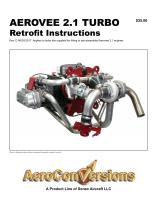
AEROVEE 2.1 TURBO Retrofit Instructions Rev. D 06/30/2017 Applies to turbo kits supplied for fitting to pre-assembled Aerovee 2.1 engines Photo for illustration only and does not represent the specific contents of your kit. A Product Line of Sonex Aircraft LLC
Open the catalog to page 1
AeroVee 2.1 Turbo Retrofit © Sonex Aircraft, All Rights Reserved Rev D 06/30/2017
Open the catalog to page 2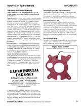
AeroVee 2.1 Turbo Retrofit Disclaimer and Limited Warranty The Experimental AeroVee Engine Kit is sold “as is”. No Warranty is expressed or implied! Sonex Aircraft LLC makes every effort to assure the supplied components of the AeroVee Engine Kit meet high quality and durability standards, and warrants to the original purchaser that these components are free of defects in material and workmanship for the period of one year from the date of purchase. This warranty does not apply to damage due directly or indirectly to improper assembly, misuse, abuse, negligence or accidents, repairs or alteration...
Open the catalog to page 3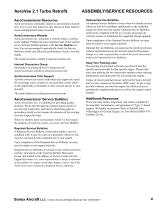
AeroVee 2.1 Turbo Retrofit AeroConversions Resources AeroConversions continually improves and monitors its products. It is in your best interest to stay abreast of these improvements and implement them as needed. AeroConversions Website AeroConversions, Inc. maintains a website which is continuously updated. Perhaps the most important part of the website for an AeroVee builder/operator is the Service Bulletin section. You are encouraged to periodically check for Service Bulletins which may affect the performance of your AeroVee engine. The AeroConversion website is aeroconversions.com Internet...
Open the catalog to page 4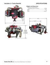
AeroVee 2.1 Turbo Retrofit SPECIFICATIONS Weights and Dimensions: © Sonex Aircraft, All Rights Reserved Rev D 06/30/201
Open the catalog to page 5
AeroVee 2.1 Turbo Retrofit General Specifications (Subject to change without notice) Power and Displacement: SPECIFICATIONS Firing Order The AeroVee has a "wasted spark" ignition system which allows the spark plugs to fire on non-combustion strokes as well as combustion strokes. The arrows in this diagram illustrate the order of combustion. CYLINDER NUMBERING, FIRING ORDER, and ENGINE ORIENTATION Front Right Cylinder Identification, Engine Orientation, and Firing Order Cylinder Identification For assembly and maintenance, the AeroVee uses the cylinder identification numbers shown below. Operating...
Open the catalog to page 6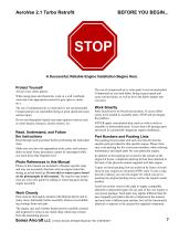
A Successful, Reliable Engine Installation Begins Here. Protect Yourself Always wear safety glasses When using paint and chemicals, work in a well ventilated room and wear appropriate protective gear (gloves, mask, etc.). The use of compressed air to clean parts is not recommended. Compressed air can send debris flying at great speed and cause serious injury. Do not use flammable liquids near open ignition sources such as water heaters, furnaces, electric motors, etc. Read, Understand, and Follow the Instructions Read through each procedure before performing the individual steps. Make sure you...
Open the catalog to page 7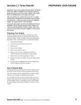
AeroVee 2.1 Turbo Retrofit PREPARING YOUR ENGINE Important: The Aerovee engine has been sold in various kit forms since 2000. In addition to the numerous engine upgrades released by AeroConversions, builder's have made their own modifications; some small, some large. These instructions are written for an AeroVee 2.1 engine than has been assembled correctly from AeroConversions'provided parts. AeroConversions provide no installation support for engines that have been modified. Your particular engine may also need additional items not included in Turbo Upgrade package. Some of these may need to...
Open the catalog to page 8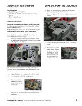
DUAL OIL PUMP INSTALLATION AeroVee 2.1 Turbo Retrofit Parts Required: __ Dual Oil Pump, ACV-T05-47 __ ACV-T05-69, M8x1.25 x 50mm Socket Cap Screws, (Qty. 4) __ White Lithium Grease __6. Install the secondary pump. Make sure the lug of the driven gear engages the slot in the cam. Note: Any "alignment" marks on the pump gears can be ignored. Assembly Instructions Important: Disassemble the oil pump carefully and deliberately, paying close attention to the orientation and location of each component. Be particularly watchful for the two small alignment pins between the two pump halves, as they can...
Open the catalog to page 9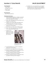
VALVE ADJUSTMENT AeroVee 2.1 Turbo Retrofit __13. Install the valve covers using the valve cover gaskets, hex head cap screws, O-rings, and washers included with the valve covers. The cap screws are tightened by feel to secure the covers and prevent leaks. Tools Required: __ Feeler Gauges __ Flat blade screw driver __ Socket Wrench __ 13 mm Socket Parts Required: __ Valve Covers, ACV-P01-15 Assembly Instructions: __ 1. Rotate the prop hub until the # 1 cylinder is at top dead center and both the intake and the exhaust valves are closed (valve springs fully extended). __ 2. Insert a .008" feeler...
Open the catalog to page 10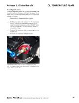
AeroVee 2.1 Turbo Retrofit Assembly Instructions The turbo installation requires the oil temperature sender to be located in the block-off plate at the front of the engine. If your engine already has the temperature sender in this location you can skip this section. __ 1. Remove the Oil Temperature block-of plate. __ 2. Drill and tap a hole in the center of the Oil Temperature Plate to accept the oil temperature sender. If you are using the optional temperature sender offered by Sonex Aircraft you will drill a 1/2" diameter hole and tap it with a M14x1.5 tap. __ 3. Re-install the temperature...
Open the catalog to page 11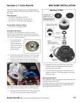
AeroVee 2.1 Turbo Retrofit MINI SUMP INSTALLATION The turbo installation requires the use of the Mini Sump. If your engine already has the Mini Sump installed you can skip this section. Parts Required: __ ACV-P06-75, Mini Sump with Filter __ ACV-Z01-22, 6mm Elastic Stop Nut (Qty. 6) __ ACV-Z01-83, 1/4 NPT Brass Pipe Plug (Qty. 1) Service Parts to Keep on Hand: __ ACV-P01-54, Oil Change Gaskets Assembly Instructions: Note: Refer to the exploded photo and the instructions included with the Mini Sump (and reproduced on this page) while installing the mini sump. The following additional notes will...
Open the catalog to page 12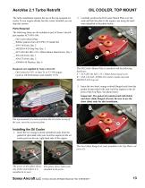
AeroVee 2.1 Turbo Retrofit 2. Carefully position the Oil Cooler Mount Plate over the seals and bolt the plate to the engine case using the hardware identified in the photo below. The turbo installation requires the use of the top-mounted oil cooler. If your engine already has this cooler installed you can skip this section. Parts Required The following items are all included as part of Sonex Aircraft part number ACV-P01-106: __ Oil Cooler Mount Plate __ Rubber gaskets from ACV-P02-15 Gasket Kit __ AN4-14A bolt, Qty. 2 __ MS20365-428 Stop Nut, Qty. 3 __ ACV-Z01-80, M8-1.25 x 20mm Button Head Screw,...
Open the catalog to page 13All AeroConversions catalogs and technical brochures
 AeroVee 2.1
71 Pages
- 4-stroke piston engine
- ULM piston engine
- Pressure sensor for the aerospace industry
- Aircraft pressure sensor
- 50 - 100kg piston engine
- Braking system
- 4-cylinder piston engine
- Temperature sensor for the aerospace industry
- Aircraft temperature sensor
- Aircraft spinner
- Absolute pressure sensor
- 50 - 100hp piston engine
- Two-bladed aircraft spinner
- Composite aircraft spinner
- Digital pressure sensor
- Thermocouple temperature sensor
- Aircraft brake
- Brake
- Light aircraft brake
- Aluminum aircraft spinner