- Catalogs
- AeroConversions
- AeroVee 2.1
AeroVee 2.1

AeroVee 2.1
This document serves as the assembly and installation manual for the AeroVee 2.1 engine kit, applicable to serial numbers 0440 and up. It provides comprehensive instructions for assembling and installing the engine, with a focus on the top-mounted oil cooler configuration. The manual stresses the importance of adhering to the instructions and offers contact information for technical support.
The engine weighs 160 lbs without oil and exhaust, with dimensions of 24.25” in length, 30” in width, and 20.0625” in height. It delivers a maximum power of 80 HP at 3400 RPM, with a displacement of 2180cc and adjustable compression ratios for different fuel types. The ignition system is fixed at 28° BTDC, and the engine features a direct propeller drive.
Detailed step-by-step procedures are provided for assembling components such as the crankshaft, cam, connecting rods, and pistons. Instructions for installing the cylinder head, rocker shaft, oil screen, and oil pump are included, with specific guidance for both top and bottom mount oil cooler installations.
Instructions cover engine installation onto the aircraft, including firewall preparation, alternator and voltage regulator installation, and ignition system wiring. The manual also details the installation of the exhaust system, engine cooling baffles, and fuel supply.
Guidelines for engine start-up, break-in, and regular maintenance are provided, specifying minimum maintenance intervals and torque values for components. Troubleshooting tips and electrical schematics are included.
AeroConversions issues service bulletins for parts or procedures requiring attention. The manual encourages staying updated with these bulletins and provides resources for additional support, including an internet discussion group and technical support via email.
The AeroVee engine kit is sold "as is" with no expressed or implied warranty. The manual outlines a limited warranty on components and emphasizes the user's responsibility for proper assembly and operation, including a disclaimer regarding liability for damages.
Additional details on installing the AeroVee engine on specific airframes are provided, along with a revision log and part numbers with packing lists.
Key specifications include a maximum power of 80 HP at 3400 RPM, a displacement of 2180cc, and adjustable compression ratios. The engine features a primary air and secondary oil cooling system, with a 12v battery and 20 amp alternator.
Operating limitations include an idle RPM of 800-900, a cruise RPM of 3200 +/- 200, and a maximum RPM of 4000. Oil temperature and pressure limits are specified, along with cylinder head and exhaust gas temperature limits.
Safety precautions include wearing protective gear and avoiding compressed air for cleaning. Detailed assembly instructions emphasize cleanliness, proper lubrication, and the use of compatible replacement parts.
Key steps involve heating parts, applying grease, and careful assembly without forcing parts. Tools required include an oven, heat-proof gloves, and various wrenches.
Involves aligning the cam gear, applying Locktite, and torquing bolts. Tools required include a socket wrench and torque wrench.
Key steps involve cleaning surfaces, applying grease, and ensuring proper torque and clearance. Tools required include white lithium grease and a torque wrench.
Involves installing head studs, removing chips, and installing oil pressure relief components. Key steps include cleaning case halves and ensuring no metal chips remain.
Involves applying grease to bearings, aligning and installing the crankshaft assembly, and ensuring proper torque sequence for nuts.
Involves matching pistons and pins, measuring deck height, and applying sealant to shims and cylinder base.
Ensure all components are clean and lubricated before installation, follow torque specifications, and use appropriate shims and sealants.
Involves securing the plate below cylinder #2 with nuts and a gasket, with an option to modify for an oil temperature probe.
Involves using high-temperature silicone sealant and torquing the gland nut to 227 ft-lbs.
Involves attaching ignition modules and securing the plate to the engine case.
Involves aligning the shaft with the flywheel and applying Locktite to screws.
Involves gapping plugs and applying anti-seize compound to threads.
Involves securing intake elbow spacers and elbows with RTV and attaching the AeroInjector.
Involves fitting the stator assembly and ensuring clearance with the magnet ring.
Involves preparing the firewall for mounting ignition coils and a voltage regulator.
Involves using motor mount shock bushings and washers, with lubrication to aid installation.
Involves using a DPST toggle switch for control and ensuring proper grounding.
Outlines wiring for the secondary ignition system, emphasizing proper grounding and connection.
Describes the process for initial timing and checking timing accuracy.
Provides instructions for connecting the alternator to the voltage regulator and battery.
Includes attaching the starter to the accessory plate and advising on electrical connections.
Provides instructions for forming and installing the breather tube.
Outlines options for oil cooler installations and highlights the availability of AeroVee Firewall Forward Kits.
Details bottom and top mount oil cooler installations and bypass options.
Involves attaching manifolds to cylinder heads and securing pipes with springs and clamps.
Includes installing a gascolator and using stainless steel reinforced fuel lines.
Requires a baffle system to direct air over the piston barrels and cylinder heads.
Offers fence baffle systems for Sonex airframes, adaptable for other installations.
Specifies oil types for optimal performance, with specific requirements during the break-in period.
Involves adding oil and ensuring proper oil pressure before operation.
Emphasizes safety during start-up and outlines the break-in process.
Outlines regular maintenance tasks and intervals.
Provides a guide for common engine issues and remedies.
Includes quick reference schematics for various subsystems.
Provides technical specifications and installation guidelines for the AeroVee 2.1 engine, focusing on cowling and exhaust systems for Sonex Aircraft models.
Outlines dimensions and locations for cowl openings and exhaust outlets.
Includes instructions for fitting cowls and custom exhaust installations.
Emphasizes the importance of proper cooling inlets and exhaust outlets.
Details changes made to the manual over time.
Advises retaining packing lists for reference when ordering parts.
Catalog excerpts

Rev AC. 03/10/2017 Applies to AeroVee s/n 0440 and up. Includes top-mounted oil cooler. Photo for illustration only and does not represent the specific contents of your kit. A Product Line of Sonex Aircraft LLC
Open the catalog to page 1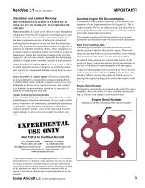
AeroVee 2.1 Rev AC. 03/10/2017 Disclaimer and Limited Warranty The Experimental AeroVee Engine Kit is sold “as is”. No Warranty is expressed or implied! Sonex Aircraft LLC makes every effort to assure the supplied components of the AeroVee Engine Kit meet high quality and durability standards, and warrants to the original purchaser that these components are free of defects in material and workmanship for the period of one year from the date of purchase. This warranty does not apply to damage due directly or indirectly to improper assembly, misuse, abuse, negligence or accidents, repairs or alteration...
Open the catalog to page 3
ASSEMBLY/SERVICE RESOURCES AeroConversions Resources AeroConversions continually improves and monitors its products. It is in your best interest to stay abreast of these improvements and implement them as needed. AeroConversions Website AeroConversions, Inc. maintains a website which is continuously updated. Perhaps the most important part of the website for an AeroVee builder/operator is the Service Bulletin section. You are encouraged to periodically check for Service Bulletins which may affect the performance of your AeroVee engine. The AeroConversion website is aeroconversions.com AeroVee...
Open the catalog to page 4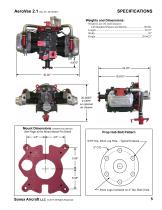
SPECIFICATIONS Weights and Dimensions: Mount Dimensions (Viewed from behind) See Page 40 for Motor Mount Pin Detail 4.8" Prop Hub Bolt Pattern 4.8" 9/16" Dia. Drive Lug Hole - Typical 6 places 5" O.D. Drive Lugs Centered on 4" Dia. Bolt Circle
Open the catalog to page 5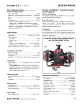
AeroVee 2.1 Rev AC. 03/10/2017 General Specifications (Subject to change without notice) Power and Displacement: SPECIFICATIONS Cylinder Identification, Engine Orientation, and Firing Order Cylinder Identification For assembly and maintenance, the AeroVee uses the cylinder identification numbers shown below. Engine Orientation When referencing the location / orientation of items on the engine, "Front", "Back", "Left", and "Right" are used as if the engine is installed in a tractor configuration and viewed from behind the engine, as shown below. Firing Order The AeroVee has a "wasted spark" ignition...
Open the catalog to page 6
A Successful, Reliable Engine Installation Begins Here. Protect Yourself Always wear safety glasses When using paint and chemicals, work in a well ventilated room and wear appropriate protective gear (gloves, mask, etc.). The use of compressed air to clean parts is not recommended. Compressed air can send debris flying at great speed and cause serious injury. Do not use flammable liquids near open ignition sources such as water heaters, furnaces, electric motors, etc. Read, Understand, and Follow the Instructions Read through each procedure before performing the individual steps. Make sure you...
Open the catalog to page 7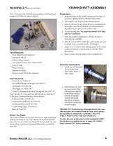
AeroVee 2.1 Rev AC. 03/10/2017 Note: If you have the optional pre-assembled crank shaft (part number ACV-H01-20), skip to Step 10. CRANKSHAFT ASSEMBLY Preparation: __ 1. Inspect the bore of the Crank Timing Gear for burrs. If necessary, lightly polish it with fine emery cloth. __ 2. Thoroughly clean all parts with Mineral Spirits. __ 3. Remove the four (4) hex plugs from the crankshaft and thoroughly clean the crankshaft with Mineral Spirits. Re-install the hex plugs with Locktite #242. __ 4. Test fit the prop hub. The prop hub should NOT slide onto the crankshaft. __ 5. Place the cleaned crankshaft...
Open the catalog to page 8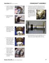
CRANKSHAFT ASSEMBLY __ 3. Install the Timing Gear with the two machined dots (arrow in photo) facing away from bearing #2. __9. Align the keyway of the Prop Hub with the forward woodruff key installed in the crankshaft and tap the prop hub into place using a mallet and block of wood. The prop hub must be tight against the oil slinger. __ 4. Install the Retaining Ring in the groove in the crank. Immediately install Prop Hub Bushing and Washer and Bolt (ACV-Z01-74). Use an impact wrench to tighten the bolt and push the prop hub against the oil slinger. __ 5. Enlarge the oil supply hole in bearing...
Open the catalog to page 9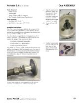
AeroVee 2.1 Rev AC. 03/10/2017 Tools Required: __ Socket Wrench __ 13mm Socket __ Torque Wrench (20 ft.-lbs. capacity) __ "Red" Locktite (High Strength Threadlocker) Parts Required: __ Cam Gear, ACV-P01-49 __ Cam Shaft (w/ hardware), ACV-P01-72 CAM ASSEMBLY __1. Align the machined dot on the face of the Cam Gear (arrow in photo) with the slot in the Cam Shaft. Apply Red Locktite to the bolts and install the bolts and washers (if provided). __2. Torque the bolts to 20 ft-lbs. Assembly Instructions: Note: The Assembly Lube provided with the cam gear will be used to lubricate the valve lifters in...
Open the catalog to page 10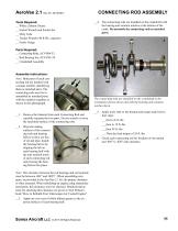
Tools Required: __ White Lithium Grease __ Socket Wrench and Socket Set __ Moly Lube __ Torque Wrench (40 ft-lbs. capacity) __ Feeler Gauge __4. The connecting rods are installed on the crankshaft with the bearing anti-rotation notches at the bottom of the crank. Re-assemble the connecting rods as matched parts. 4 Parts Required: __ Connecting Rods, ACV-P06-33 __ Rod Bearing Set, ACV-P01-59 __ Crankshaft Assembly Assembly Instructions: Note: Both parts of each connecting rod are marked with a unique number, identifying them as matched parts. The connecting rods must be reassembled as matched...
Open the catalog to page 11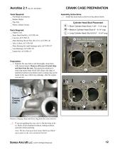
CRANK CASE PREPARATION Assembly Instructions: __1. Install the head studs as shown in the photos below. Tools Required: __ Flat Blade Screwdriver __ Rubber Mallet __ Fine File __ White Lithium Grease Cylinder Head Stud Placement S = Short Cylinder Head Stud (7-3/8" - 7-1/2" long) Parts Required: __ Engine Case __ 8mm Head Stud Kit, ACV-P01-86 __ Case kit, ACV-P02-12 __ Main Bearing Dowel Pins (Set of 5), ACV-P01-46 __ Valve Lifters, ACV-P01-48 __ Main Bearing Set (split bearings only), ACV-P01-57 __ Cam Bearings, ACV-P01-58 __ Gasket Set, ACV-P02-15 M = Medium Cylinder Head Stud (8" - 8-1/4"...
Open the catalog to page 12All AeroConversions catalogs and technical brochures
 AeroVee Turbo
33 Pages
- 4-stroke piston engine
- ULM piston engine
- Pressure sensor for the aerospace industry
- Aircraft pressure sensor
- 50 - 100kg piston engine
- Braking system
- 4-cylinder piston engine
- Temperature sensor for the aerospace industry
- Aircraft temperature sensor
- Aircraft spinner
- Absolute pressure sensor
- 50 - 100hp piston engine
- Two-bladed aircraft spinner
- Composite aircraft spinner
- Digital pressure sensor
- Thermocouple temperature sensor
- Aircraft brake
- Brake
- Light aircraft brake
- Aluminum aircraft spinner