
カタログの抜粋
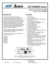
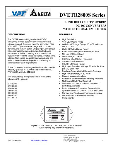
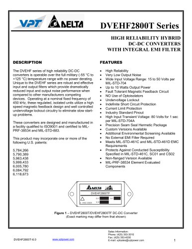
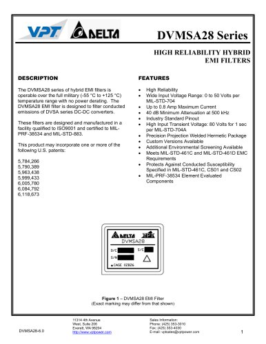
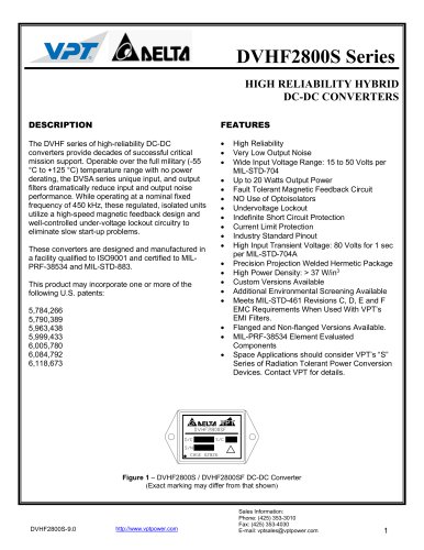
DVTR2800S SeriesHIGH RELIABILITY HYBRID DC-DC CONVERTERS DESCRIPTION The DVTR series of high-reliability DC-DC converters provide decades of successful critical mission support. Operable over the full military (-55 °C to +125 °C) temperature range with no power derating, the DVTR series unique input, and output filters dramatically reduce input and output noise performance. While operating at a nominal fixed frequency of 450 kHz, these regulated, isolated units utilize a high-speed magnetic feedback design and well-controlled under-voltage lockout circuitry to eliminate slow start-up problems. These converters are designed and manufactured in a facility qualified to ISO9001 and certified to MIL-PRF-38534 and MIL-STD-883. This product may incorporate one or more of the following U.S. patents: 5,784,266 5,790,389 5,963,438 5,999,433 6,005,780 6,084,792 6,118,673 FEATURES • High Reliability • Very Low Output Noise • Wide Input Voltage Range: 15 to 50 Volts per MIL-STD-704 • Up to 40 Watts Output Power • Fault Tolerant Magnetic Feedback Circuit • Output Voltage Trim Up +10% • NO Use of Optoisolators • Undervoltage Lockout • Indefinite Short Circuit Protection • Current Limit Protection • Industry Standard Pinout • High Input Transient Voltage: 80 Volts for 1 sec per MIL-STD-704A • Precision Seam Seal Hermetic Package • High Power Density: > 40 W/in3 • Custom Versions Available • Additional Environmental Screening Available • Meets MIL-STD-461 Revisions C, D, E and F EMC Requirements When Used With VPT’s EMI Filters • Flanged and Non-flanged Versions Available • MIL-PRF-38534 Element Evaluated Components • Space Applications should consider VPT’s "S” Series of Radiation Tolerant Power Conversion Devices. Contact VPT for details. Sales Information: Phone: (425) 353-3010 Fax: (425) 353-4030 E-mail: vptsales@vptpower.com
カタログの1ページ目を開く
Notes: 1. Dependent on output voltage. 2. Time for output voltage to settle within 1% of its nominal value. 3. Derate linearly to 0 at 135°C. 4. Verified by initial electrical design verification. Post design verification, parameter shall be guaranteed to the limits specified. 5. Correction factor of 0.12 added to ceramic capacitors.
カタログの2ページ目を開く
Notes: 1. Dependent on output voltage. 2. Time for output voltage to settle within 1% of its nominal value. 3. Derate linearly to 0 at 135°C. 4. Verified by initial electrical design verification. Post design verification, parameter shall be guaranteed to the limits specified. 5. Correction factor of 0.12 added to ceramic capacitors.
カタログの3ページ目を開く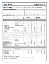
Notes: 1. Dependent on output voltage. 2. Time for output voltage to settle within 1% of its nominal value. 3. Derate linearly to 0 at 135°C. 4. Verified by initial electrical design verification. Post design verification, parameter shall be guaranteed to the limits specified. 5. Correction factor of 0.12 added to ceramic capacitors.
カタログの4ページ目を開く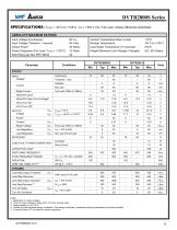
Notes: 1. Dependent on output voltage. 2. Time for output voltage to settle within 1% of its nominal value. 3. Derate linearly to 0 at 135°C. 4. Verified by initial electrical design verification. Post design verification, parameter shall be guaranteed to the limits specified. 5. Correction factor of 0.12 added to ceramic capacitors.
カタログの5ページ目を開く
Notes: 1. Dependent on output voltage. 2. Time for output voltage to settle within 1% of its nominal value. 3. Derate linearly to 0 at 135°C. 4. Verified by initial electrical design verification. Post design verification, parameter shall be guaranteed to the limits specified. 5. Correction factor of 0.12 added to ceramic capacitors.
カタログの6ページ目を開く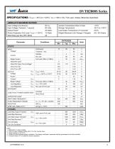
Notes: 1. Dependent on output voltage. 2. Time for output voltage to settle within 1% of its nominal value. 3. Derate linearly to 0 at 135°C. 4. Verified by initial electrical design verification. Post design verification, parameter shall be guaranteed to the limits specified. 5. Correction factor of 0.12 added to ceramic capacitors.
カタログの7ページ目を開く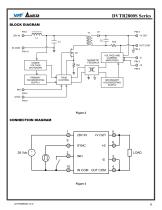
DVTR2800S Series BLOCK DIAGRAM PIN 1 UNDER VOLTAGE SHUTDOWN PRIMARY HOUSEKEEPING SUPPLY VOLTAGE AND CURRENT AMPLIFIERS SECONDARY HOUSEKEEPING SUPPLY CONNECTION DIAGRAM
カタログの8ページ目を開く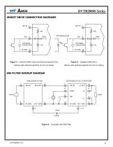
DVTR2800S Series INHIBIT DRIVE CONNECTION DIAGRAMS OPTIONAL CAPACITOR OPTIONAL CAPACITOR Figure 4 – Internal Inhibit Circuit and Recommended Drive Figure 5 – Isolated Inhibit Drive (Shown with optional capacitor for turn-on delay) (Shown with optional capacitor for turn-on delay) EMI FILTER HOOKUP DIAGRAM Figure 6 – Converter with EMI Filter
カタログの9ページ目を開く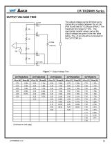
The output voltage can be trimmed up by connecting a resistor between the +S pin (PIN 6) and the OUT COM pin (PIN 4). The maximum trim range is +10%. The appropriate resistor values versus the output voltage are given in the trim table below. The -S pin should be connected to the OUT COM pin. (Continued on next page)
カタログの10ページ目を開く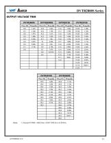
Notes: 1. Connect R-TRIM = 400Q from +VOUT (PIN 5) to +S (PIN 6).
カタログの11ページ目を開く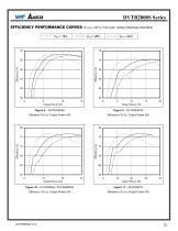
DVTR2800S Series EFFICIENCY PERFORMANCE CURVES (TCASE = 25°C, Full Load, Unless Otherwise Specified) VIN = 16V Efficiency (%) vs. Output Power (W) Efficiency (%) vs. Output Power (W) Efficiency (%) vs. Output Power (W) Efficiency (%) vs. Output Power (W)
カタログの12ページ目を開く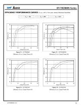
DVTR2800S Series EFFICIENCY PERFORMANCE CURVES (TCASE = 25°C, Full Load, Unless Otherwise Specified) VIN = 16V Efficiency (%) vs. Output Power (W) Efficiency (%) vs. Output Power (W) Efficiency (%) vs. Output Power (W) Efficiency (%) vs. Output Power (W)
カタログの13ページ目を開く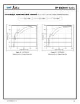
DVTR2800S Series EFFICIENCY PERFORMANCE CURVES (TCASE = 25°C, Full Load, Unless Otherwise Specified) VIN = 16V Efficiency (%) vs. Output Power (W) Efficiency (%) vs. Output Power (W)
カタログの14ページ目を開く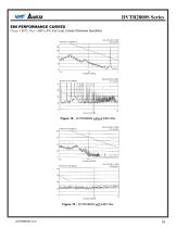
DVTR2800S Series EMI PERFORMANCE CURVES (TCASE = 25°C, VIN = +28V ± 5%, Full Load, Unless Otherwise Specified) Figure 18 – DVTR2800S without EMI Filter Figure 19 – DVTR2800S with EMI Filter
カタログの15ページ目を開く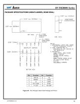
Figure 20 - Non-Flanged, Seam Seal Package and Pinout
カタログの16ページ目を開く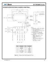
Figure 21 - Flanged, Seam Seal Package and Pinout
カタログの17ページ目を開く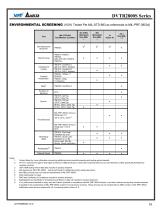
DVTR2800S SeriesENVIRONMENTAL SCREENING (100% Tested Per MIL-STD-883 as referenced to MIL-PRF-38534) Test 1. Contact Sales for more information concerning additional environmental screening and testing options desired. 2. VPT Inc. reserves the right to ship higher screened or SMD products to meet lower screened orders at our sole discretion unless specifically forbidden by customer contract. 3. 100% R&R testing with all test data included in product shipment. 4. Not required per MIL-PRF-38534. Test is performed for additional product quality assurance. 5. Non-QML products may not meet all...
カタログの19ページ目を開くVPT INC.のすべてのカタログと技術パンフレット
-
 DVETR2800S
16 ページ
-
 DVEHF2800T
12 ページ
-
 DVPL0510S
13 ページ
-
 DVPL0505S
13 ページ
-
 DVPL0503S
12 ページ
-
 DVMSA28
9 ページ
-
 DVFL2800D
28 ページ
-
 DVFL2800S
30 ページ
-
 DVHE2800S
15 ページ
-
 DVTR2800D
21 ページ
-
 DVTR2800T
15 ページ
-
 DVWR2800T
14 ページ
-
 DVHF2800D
17 ページ
-
 DVHF2800S
18 ページ
-
 DVAB2800D
14 ページ
-
 DVHF+2800T
17 ページ
-
 DVHV2800D
17 ページ
-
 DVSB2800D
14 ページ
-
 DVHV2800S
17 ページ
-
 DVGF+2800T
15 ページ
-
 DVSA2800D
16 ページ
-
 DVSA2800S
15 ページ
-
 DVCH2800S
14 ページ