
カタログの抜粋

CONNECTOR SERIES PCB Connectors
カタログの1ページ目を開く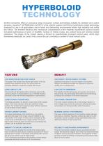
Smiths Connectors offers an extensive range of superior contact technologies suitable for standard and custom solutions. Hypertac® (HYPERboloid conTACT) is the original superior performing hyperboloid contact technology designed for use in all applications and in harsh and demanding environments where high reliability and safety are critical. The inherent electrical and mechanical characteristics of the Hypertac hyperboloid contact ensures unrivalled performance in terms of reliability, number of mating cycles, low contact force and minimal contact resistance. The shape of the contact...
カタログの2ページ目を開く
smiths connectors ► Receptacle connector: 42, 82, 110, 126, 158 and 174 socket contact positions ..17
カタログの3ページ目を開く
1. SCOPE 1.1 Scope This Design covers CMD Connectors Family, plug and receptacle style, with 42, 82, 110, 126, 158, 174, 220, 236 and 316 pin or socket contact positions, conforming to MIL-C-55302. Contact arrangement is offset-grid pattern within dielectric connector body with four rows, .075 in (1.905 mm) center-to-center contact spacing in each row, and .075 in (1.905 mm) row-to-row spacing. Contact size is 0.6 mm nominal pin DIA.Polarization feature is incorporated in each connector assembly to assure correct insertion. Coding key system provides 36 possible keying combinations. There...
カタログの4ページ目を開く
2. APPLIED DOCUMENTS 2.1 Applied documents CMD Connectors Family is designed, manufactured, tested and delivered in accordance with the documents listed below. The latest issue of the following documents, documents amendments and notices, in being on 30 June 1994 are used unless otherwise specified in this Design. MIL-C-26074 Coatings, electroless nickel requirement for. MIL-I-46058 Insulating compound, electrical (for coating printed circuit assemblies). MIL-P-50884 Printed-wiring, flexible and rigid-flex. MIL-C-55302 Connectors, printed circuit subassembly and accessories. MIL-I-81550...
カタログの5ページ目を開く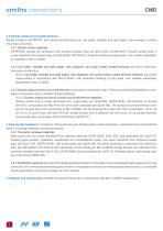
3.3 Socket contact and contact terminal Socket contact is HYPERTAC and contact terminal types are: dip solder, (straight and right angle), wire wrappost, surface mount tail, and crimp. 3.3.1 Socket contact materials HYPERTAC springs are wiredrawn from beryllium-copper alloy per QQ-C-530, (ASTM B197). Socket contact body is screw machined from copper-alloy per QQ-B-626, (ASTM B16). Protective finishing is gold plate, over suitable underplate, as specified in MIL-C-55302. 3.3.2 Dip solder, (straight and right angle), wire wrappost, and crimp socket contact terminals are screw machined,...
カタログの6ページ目を開く
3.6 CMD Connectors Family requirements are: - contact engagement and separation forces: maximum engagement force =100 g (3.53 oz); minimum separation force =14 g (.49 oz); - connector mating and unmating forces: maximum mating force =60 g (2.12 oz) multiplied by number of contacts;minimum unmating force =20 g (.71 oz) multiplied by number of contacts; - contact current rating: the connector may have any combination of current flow and ambient temperature provided the contact or connector temperature does not exceed 125 °C. If mated plug and receptacle connectors are both equipped with dip...
カタログの7ページ目を開く
smiths connectorsSELECTION CHART B++ + + + + + + + • ®+ + + + + + + + © \vy Connector figure (mating face) •+++++++++++++++++++++++++++++++++++++• •+++++++++++++++++++++++++++++++++++++• •+++++++++++++++++++++++++++++++++++++• 1} •+++++++++++++++++++++++++++++++++++++• plug connector body equipped with dip solder, straight thru, contact terminal. plug connector body equipped with all the other contact terminal styles.
カタログの8ページ目を開く
smiths connectors Contact terminal types available are: Contact positions Connector style Dip solder Plug connector pin contacts equipped (Straight thru) Yes (Right angle) Yes Surface Wire mount wrap tail post Check Firm 42 Receptacle connector socket contacts equipped Check Firm Plug connector pin contacts equipped Check Firm 82 Receptacle connector socket contacts equipped Check Firm Plug connector pin contacts equipped 110 Receptacle connector socket contacts equipped Plug connector pin contacts equipped Check Firm 126 Receptacle connector socket contacts equipped Check Firm...
カタログの9ページ目を開く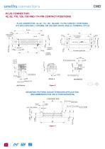
CMD PLUG CONNECTOR: 42, 82, 110, 126, 158 AND 174 PIN CONTACT POSITIONS PLUG CONNECTOR: 42, 82, 110, 126, 158 and 174 PIN CONTACT POSITIONS, .075 INCH SPACING (1.905 mm), DIP SOLDER (RIGHT ANGLE) TERMINAL STYLE A max B D-shaped guide pins MOUNTING PATTERN, DAUGHTERBOARD APPLICATION, (RECOMMENDED PCB HOLE CONFIGURATION) COMPONENT SIDE C 5.08 Last hole position 4.00 Last contact posi
カタログの10ページ目を開く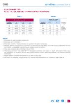
smiths connectorsPLUG CONNECTOR: 42, 82, 110, 126, 158 AND 174 PIN CONTACT POSITIONS TABLE I TABLE II Dimensions in width 1. Dimensions for user installation purpose only. 3. Dimensions in width of these connectors are specified in the table I of this page. 4. Materials, finishes and connectors requirements are described into this catalog. Hot solder dipping,as dip solder terminal end finishing, is available at Customer request, (please consult the Factory). 5. These plug connectors are conforming to MIL-C-55302. 6. These plug connectors mate CMD***EF****H receptacle connectors, (see...
カタログの11ページ目を開く
1 connector family 2 connector size 5 contact terminal style Dip solder, right angle, with: A .109 inch (2.76 mm) long dip Y D-shaped guide pins P universal coupling guide pins (for test type connectors) 0 0 When D-shaped guide pins are installed in the 01 polarized position, (see polarization configuration chart on page 44), without Loctite 242 applied. 0 1 to 3 6 When D-shaped guide pins are installed in the proper polarized position and Loctite 242 is applied to the threads, (see polarization configuration chart on page 44). 3 7 When universal coupling guide pins, (for test type...
カタログの12ページ目を開く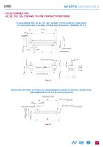
CMD PLUG CONNECTOR: 42, 82, 110, 126, 158 and 174 PIN CONTACT POSITIONS PLUG CONNECTOR: 42, 82, 110, 126, 158 and 174 PIN CONTACT POSITIONS, .075 INCH SPACING (1.905 mm), DIP SOLDER (STRAIGHT) TERMINAL STYLE A max B Last contact position D-shaped guide pins MOUNTING PATTERN, IN PARALLEL ARRANGEMENT BOARD-TO-BOARD CONNECTION, (RECOMMENDED PCB HOLE CONFIGURATION) COMPONENT SIDE Ø 0.70 min = LAST HOLE POSITION
カタログの13ページ目を開くSmiths Connectorsのすべてのカタログと技術パンフレット
-
 Semiconductor
20 ページ
-
 HBB CONNECTOR SERIES
24 ページ
-
 HDLP SERIES
8 ページ
-
 C9394
C939436 ページ
-
 COAXIAL CONNECTORS
1 ページ
-
 cpcI SERIES
16 ページ
