
カタログの抜粋

OPERATING INSTRUCTION WT100-2 with background suppression Miniature photoelectric sensor
カタログの1ページ目を開く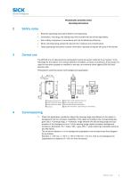
Sensor Intelligence. Photoelectric proximity sensor Operating instructions Read the operating instructions before commissioning. Connection, mounting, and setting may only be performed by trained specialists. Not a safety component in accordance with the EU Machinery Directive. When commissioning, protect the device from moisture and contamination. These operating instructions contain information required during the life cycle of the sensor. The WT100-2 is an opto-electronic photoelectric proximity sensor (referred to as "sensor" in the following) for the optical, non-contact detection of...
カタログの2ページ目を開く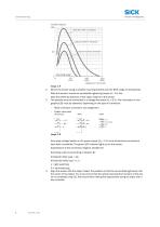
Commissioning Function reserve 100 white 90 %/90 % remission Operating range Distance in mm (inch) Image 1: H Mount the sensor using a suitable mounting bracket (see the SICK range of accessories). Note the sensor's maximum permissible tightening torque of < 0.5 Nm. Note the preferred direction of the object relative to the sensor. The sensors must be connected in a voltage-free state (VS = 0 V). The information in the graphics [B] must be observed, depending on the type of connection: – Male connector connection: pin assignment – Cable: core color Only apply voltage/switch on the power...
カタログの3ページ目を開く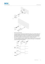
Sensor with potentiometer: The sensing range is adjusted with the potentiometer (type: 270°). Clockwise rotation: sen‐ sing range increased; counterclockwise rotation: sensing range reduced. We recommend placing the switching state in the object, e.g., see Graphic F. Once the sensing range has been adjusted, the object is removed from the path of the beam, which causes the back‐ ground to be suppressed and the switching output to change (see Graphic C). The sensor is adjusted and ready for operation. Refer to Graphics C and G to check the func‐ tion. If the switching output fails to behave...
カタログの4ページ目を開く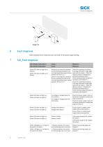
Fault diagnosis Table indicates which measures are to be taken if the sensor stops working. Tab_Fault diagnosis LED indicator/fault pattern / Green LED does not light up or flickers / Sensor is still ready for operation, but the operating conditions are not ideal (operating reserve factor between 0.9 and 1.1) / Green LED does not light up or flickers Green LED does not light up / Green LED does not light up Check the operating conditions: Fully align the beam of light (light spot) with the object. / Clean the optical surfaces / Readjust the Sensor is still ready for operation, sensitivity...
カタログの5ページ目を開く
Yellow LED does not light up (applies to light switching devices) or yellow LED lights up (applies to dark switching devices), object is in the path of the beam / / Distance between the sensor and the background is too short / Reduce the sensing range, see Graphic F / / Distance between the sensor and the background is too short Reduce the sensing range, see Graphic F Yellow LED does not light up (applies to light switching devices) or yellow LED lights up (applies to dark switching devices), object is in the path of the beam Yellow LED does not light up (applies to light switching devices)...
カタログの6ページ目を開く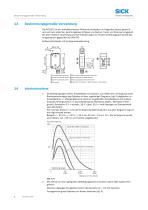
BestimmungsgemaBe Verwendung Sensor Intelligence. Die WT100-2 ist ein optoelektronischer Reflexions-Lichttaster (im Folgenden Sensor genannt) und wird zum optischen, beruhrungslosen Erfassen von Sachen, Tieren und Personen eingesetzt. Bei jeder anderen Verwendung und bei Veranderungen am Produkt verfallt jeglicher Gewahrleis- tungsanspruch gegenuber der SICK AG. 2 Den Sensor an einen geeigneten Befestigungswinkel montieren (siehe SICK-Zubehor-Pro- Maximal zulassiges Anzugsdrehmoment des Sensors von < 0.5 Nm beachten. Vorzugsrichtung des Objektes zum Sensor beachten [vgl. A].
カタログの7ページ目を開く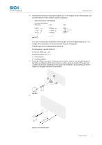
Anschluss der Sensoren muss spannungsfrei (VS = 0 V) erfolgen. Je nach Anschlussart sind die Informationen in den Grafiken [vgl. B] zu beachten: – Steckeranschluss: Pinbelegung – Leitung: Adernfarbe Erst nach Anschluss aller elektrischen Verbindungen die Spannungsversorgung (VS > 0 V) anlegen bzw. einschalten. Am Sensor leuchtet die grüne Anzeige-LED. Erläuterungen zum Anschlussschema (Grafik B): Schaltausgang Q (gemäß Grafik B): WT100-2P (PNP: Last -> M) WT100-2N (NPN: Last -> L+) L = hellschaltend 4 D = dunkelschaltend Sensor auf Objekt ausrichten. Positionierung so wählen, dass der rote...
カタログの8ページ目を開く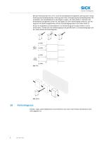
Mit dem Potentiometer (Art: 270°) wird der Schaltabstand eingestellt. Drehung nach rechts: Erhöhung des Schaltabstandes, Drehung nach links: Verringerung des Schaltabstandes. Wir empfehlen, den Schaltabstand in das Objekt zu legen, z.B. siehe Grafik F. Nachdem der Schaltabstand eingestellt worden ist, das Objekt aus dem Strahlengang entfernen, der Hin‐ tergrund wird dabei ausgeblendet und der Schaltausgang ändert sich (siehe Grafik C). Sensor ist eingestellt und betriebsbereit. Zur Überprüfung der Funktion Grafik C und G heranziehen. Verhält sich der Schaltausgang nicht gemäß Grafik C,...
カタログの9ページ目を開く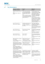
Tab_Fehlerdiagnose Anzeige-LED / Fehlerbild / Grüne LED leuchtet nicht bzw. fla‐ ckert / Sensor ist noch betriebsbereit, aber die Betriebsbedingungen sind nicht optimal (Funktionsre‐ servefaktor zwischen 0,9 und 1,1) / Green LED does not light up or flickers grüne LED leuchtet nicht / Green LED does not light up Betriebsbedingungen prüfen: Lichtstrahl (Lichtfleck) vollständig auf das Objekt ausrichten / Reini‐ gung der optischen Flächen / Empfindlichkeit (Potentiometer) Sensor is still ready for operation, neu einstellen / Schaltabstand überprüfen und ggf. anpassen, but the operating...
カタログの10ページ目を開く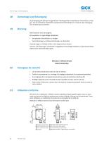
Sensor Intelligence. Die Entsorgung des Sensors hat gemaS den landerspezifisch anwendbaren Vorschriften zu erfol- gen. Fur die enthaltenen Wertstoffe (insbesondere Edelmetalle) ist im Rahmen der Entsorgung eine Verwertung anzustreben. SICK-Sensoren sind wartungsfrei. Wir empfehlen, in regelmaSigen Abstanden die optischen Grenzflachen zu reinigen Verschraubungen und Steckverbindungen zu uberprufen Veranderungen an Geraten durfen nicht vorgenommen werden. Irrtumer und Anderungen vorbehalten. Angegebene Produkteigenschaften und technische Daten stellen keine Garantieerklarung dar. Detecteur a...
カタログの11ページ目を開くSICK SENSOR INTELLIGENCEのすべてのカタログと技術パンフレット
-
 REGISTRATION SENSORS
24 ページ
-
 CLV63x, CLV64x, CLV65x
102 ページ
-
 WTB16 Bluetooth®
135 ページ
-
 WE9LC-3_A71
3 ページ
-
 Safety Switches
20 ページ
-
 Proximity Sensors
324 ページ
-
 Dust measuring devices
172 ページ
-
 Distance Sensors
404 ページ
-
 Vision
124 ページ
-
 Top-Products from SICK
556 ページ
-
 Fluid Sensors
243 ページ
-
 Registration Sensors
276 ページ
-
 Magnetic Cylinder Sensors
164 ページ
-
 IDENTIFICATION SOLUTIONS
24 ページ
-
 ConVer
12 ページ
-
 Encoders
788 ページ
-
 WT100-2 energetic
47 ページ
-
 Photoelectric Sensors
949 ページ
-
 G6 - Global Sensor
20 ページ
-
 Hand-Held Scanners IDMx
48 ページ


