
Estratti del catalogo

OPERATING INSTRUCTIONS SICK Sensor Intelligence.
Aprire il catalogo a pagina 1
OPERATING INSTRUCTIONS
Aprire il catalogo a pagina 2
Described product WTB16 - Bluetooth® Manufacturer SICK AG Erwin-Sick-Str. 1 79183 Waldkirch Germany Legal information This work is protected by copyright. Any rights derived from the copyright shall be reserved for SICK AG. Reproduction of this document or parts of this document is only permissible within the limits of the legal determination of Copyright Law. Any modifica‐ tion, abridgment or translation of this document is prohibited without the express writ‐ ten permission of SICK AG. The trademarks stated in this document are the property of their respective owner. © SICK AG. All rights...
Aprire il catalogo a pagina 3
J022691.10DR | SICK ;upject to change without notice
Aprire il catalogo a pagina 4
Safety information General safety notes Read the operating instructions before commissioning. Connection, mounting, and configuration may only be performed by trained specialists. ■ Not a safety component in accordance with the EU Machinery Directive. When commissioning, protect the device from moisture and contamination. These operating instructions contain information required during the life cycle of the sensor. Notes on UL approval The device must be supplied by a Class 2 source of supply. UL Environmental Rating: Enclosure type 1 Intended use The WTB16 Bluetooth is an opto-electronic...
Aprire il catalogo a pagina 5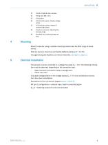
@ Center of optical axis, receiver © LED indicator green: Supply voltage active 7 LED indicator yellow: Status of received light beam © Press-turn element: Adjusting the sensing range ® BluePilot blue: Sensing range dis Mount the sensor using a suitable mounting bracket (see the SICK range of accessories). Note the sensor's maximum permissible tightening torque of < 1,3 Nm. Vorzugsrichtung des Objektes zum Sensor beachten, see figure 1, figure 2. 5 Electrical installation The sensors must be connected in a voltage-free state (UV = 0 V). The following information must be observed, depending...
Aprire il catalogo a pagina 6
Table 2: Push / pull 8022691.10DR | SICK Subject to change without notice
Aprire il catalogo a pagina 7
Alignment WTB16P Bluetooth®: Align sensor on object. Select the position so that the red emitted light beam hits the center of the object. You must ensure that the optical opening (front screen) of the sensor is completely clear [see figure 3, see figure 4]. WTB16I Bluetooth®: Align sensor on object. Select the position so that the infrared light (not visible) hits the center of the object. The correct alignment can only be detected via the LED indicators. see figure 3, figure 4 , see table 1, see table 2. You must ensure that the optical opening (front screen) of the sensor is completely...
Aprire il catalogo a pagina 8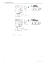
Example: Sensing range on black, 6%, A = Detection distance (depending on object remission) BluePilot; Sensing range indicator (blue LED) Teach-Turn adjustment A = Detection distance (depending on object remission) BluePilot; Sensing range indicator (blue LED) Teach-Turn adjustment Sensing range setting 8022691.10DR | SICK Subject to change without notice 8
Aprire il catalogo a pagina 9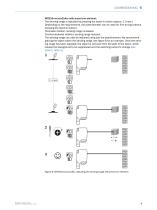
COMMISSIONING 6 WTB16x-xxxxxx2xAxx with press-turn element: The sensing range is adjusted by pressing the teach-in button (approx. 1-3 sec.). Depending on the requirements, the potentiometer can be used for fine-tuning (without pressing the teach-in button). Clockwise rotation: sensing range increased. Counterclockwise rotation: sensing range reduced. The sensing range can also be adjusted using just the potentiometer. We recommend placing the object within the sensing range, see figure 8 for an example. Once the sens‐ ing range has been adjusted, the object is removed from the path of the...
Aprire il catalogo a pagina 10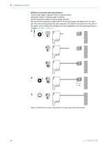
6 COMMISSIONING WTB16x-xxxxxx1xAxx with potentiometer: The sensing range is adjusted with the potentiometer. Clockwise rotation: sensing range increased. Counterclockwise rotation: sensing range reduced. We recommend placing the object within the sensing range, see figure 9 for an exam‐ ple. Once the sensing range has been adjusted, the object is removed from the path of the beam, which causes the background to be suppressed and the switching output to change (see table 1, table 2). Figure 9: WTB16x-xxxxxx1xAxx, adjusting the sensing range with potentiometer 8022691.10DR | SICK Subject to...
Aprire il catalogo a pagina 11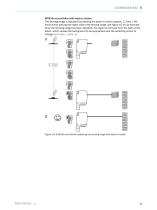
COMMISSIONING 6 WTB16x-xxxxxx3xAxx with teach-in button: The sensing range is adjusted by pressing the teach-in button (approx. 1-3 sec.). We recommend placing the object within the sensing range, see figure 10 for an example. Once the sensing range has been adjusted, the object is removed from the path of the beam, which causes the background to be suppressed and the switching output to change (see table 1, table 2). Figure 10: WTB16x-xxxxxx3xAxx, adjusting the sensing range with teach-in button 8022691.10DR | SICK Subject to change without notice
Aprire il catalogo a pagina 12
Process data structure (Version 1.1) 8022691.10DR | SICK Subject to change without notice
Aprire il catalogo a pagina 13
Disassembly and disposal The sensor must be disposed of according to the applicable country-specific regulations. Efforts should be made during the disposal process to recycle the constituent materials (particularly precious metals). NOTE Disposal of batteries, electric and electronic devices • According to international directives, batteries, accumulators and electrical or electronic devices must not be disposed of in general waste. • The owner is obliged by law to return this devices at the end of their life to the respective public collection points. This symbol on the product, its...
Aprire il catalogo a pagina 14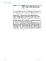
This device complies with Part 15 of the FCC Rules and with Industry Canada licence-exempt RSS standard(s). Operation is subject to the following two conditions: (1) this device may not cause harmful interference, and (2) this device must accept any interference received, including interference that may cause undesired operation. Le present appareil est conforme aux CNR d'Industrie Canada applicables aux appareils radio exempts de licence. L'exploitation est autorisee aux deux conditions suivantes: (1) l'appareil ne doit pas produire de brouillage, et (2) l'utilisateur de l'appareil doit...
Aprire il catalogo a pagina 15Tutti i cataloghi e le schede tecniche SICK SENSOR INTELLIGENCE
-
 Safety Switches
20 Pagine
-
 Magnetic Cylinder Sensors
176 Pagine
-
 Opto-Electronic Protective Devices
32 Pagine
-
 REGISTRATION SENSORS
24 Pagine
-
 CLV63x, CLV64x, CLV65x
102 Pagine
-
 WE9LC-3_A71
3 Pagine
-
 Automation light grids
8 Pagine
-
 Encoders and Inclination Sensors
32 Pagine
-
 Proximity Sensors
324 Pagine
-
 Dust measuring devices
172 Pagine
-
 Detection and Ranging Solutions
124 Pagine
-
 Distance Sensors
404 Pagine
-
 Vision
124 Pagine
-
 Top-Products from SICK
556 Pagine
-
 Fluid Sensors
243 Pagine
-
 Registration Sensors
276 Pagine
-
 IDENTIFICATION SOLUTIONS
24 Pagine
-
 FLOWSIC300 Ultrasonic Gas Flow Meter
177 Pagine
-
 FLOWSIC300 Gas flow meters
12 Pagine
-
 FLOWSIC500 Gas flow meters
16 Pagine
-
 FLOWSIC600 Ultrasonic Gas Flow Meter
138 Pagine
-
 FLOWSIC600 Gas Flow Meter
16 Pagine
-
 ConVer
12 Pagine
-
 GM32 In-situ gas analyzers
28 Pagine
-
 GM901 Carbon Monoxide Gas Analyzers
12 Pagine
-
 GM35 In-Situ IR Gas Analyzer
16 Pagine
-
 WT100-2 with background suppression
46 Pagine
-
 Encoders
788 Pagine
-
 Opto Electronic Protective Devices
712 Pagine
-
 GMS800 Extractive Gas Analyzers
20 Pagine
-
 MERCEM300Z Mercury Monitoring System
12 Pagine
-
 WT100-2 energetic
47 Pagine
-
 VPS Pro Profiling systems
20 Pagine
-
 Photoelectric Sensors
949 Pagine
-
 G6 - Global Sensor
20 Pagine
-
 Hand-Held Scanners IDMx
48 Pagine


