
Katalogauszüge
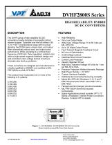
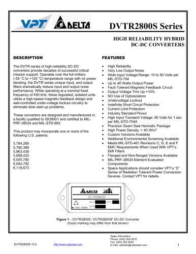
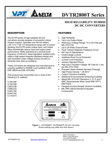
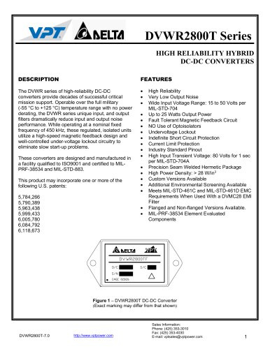
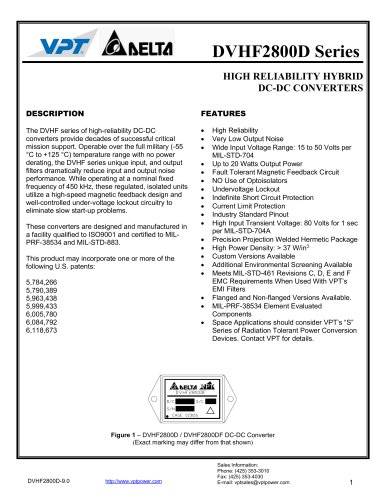
DVHF2800S SeriesHIGH RELIABILITY HYBRID DC-DC CONVERTERS DESCRIPTION The DVHF series of high-reliability DC-DC converters provide decades of successful critical mission support. Operable over the full military (-55 °C to +125 °C) temperature range with no power derating, the DVSA series unique input, and output filters dramatically reduce input and output noise performance. While operating at a nominal fixed frequency of 450 kHz, these regulated, isolated units utilize a high-speed magnetic feedback design and well-controlled under-voltage lockout circuitry to eliminate slow start-up problems. These converters are designed and manufactured in a facility qualified to ISO9001 and certified to MIL-PRF-38534 and MIL-STD-883. This product may incorporate one or more of the following U.S. patents: 5,784,266 5,790,389 5,963,438 5,999,433 6,005,780 6,084,792 6,118,673 FEATURES • High Reliability • Very Low Output Noise • Wide Input Voltage Range: 15 to 50 Volts per MIL-STD-704 • Up to 20 Watts Output Power • Fault Tolerant Magnetic Feedback Circuit • NO Use of Optoisolators • Undervoltage Lockout • Indefinite Short Circuit Protection • Current Limit Protection • Industry Standard Pinout • High Input Transient Voltage: 80 Volts for 1 sec per MIL-STD-704A • Precision Projection Welded Hermetic Package • High Power Density: > 37 W/in3 • Custom Versions Available • Additional Environmental Screening Available • Meets MIL-STD-461 Revisions C, D, E and F EMC Requirements When Used With VPT’s EMI Filters. • Flanged and Non-flanged Versions Available. • MIL-PRF-38534 Element Evaluated Components • Space Applications should consider VPT’s "S” Series of Radiation Tolerant Power Conversion Devices. Contact VPT for details. Sales Information: Phone: (425) 353-3010 Fax: (425) 353-4030 E-mail: vptsales@vptpower.com
Katalog auf Seite 1 öffnen
DVHF2800S SeriesSPECIFICATIONS (Tcase = -55°C to +125°C, Vin = +28V ± 5%, Full Load, Unless Otherwise Specified) ABSOLUTE MAXIMUM RATINGS Notes: 1. Dependent on output voltage. 2. Time for output voltage to settle within 1% of its nominal value. 3. Derate linearly to 0 at 135°C. 4. Verified by initial electrical design verification. Post design verification, parameter shall be guaranteed to the limits specified. 5. Correction factor of 0.12 added to ceramic capacitors.
Katalog auf Seite 2 öffnen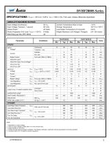
DVHF2800S SeriesSPECIFICATIONS (Tcase = -55°C to +125°C, Vin = +28V ± 5%, Full Load, Unless Otherwise Specified) ABSOLUTE MAXIMUM RATINGS Notes: 1. Dependent on output voltage. 2. Time for output voltage to settle within 1% of its nominal value. 3. Derate linearly to 0 at 135°C. 4. Verified by initial electrical design verification. Post design verification, parameter shall be guaranteed to the limits specified. 5. Correction factor of 0.12 added to ceramic capacitors.
Katalog auf Seite 3 öffnen
DVHF2800S SeriesSPECIFICATIONS (Tcase = -55°C to +125°C, Vin = +28V ± 5%, Full Load, Unless Otherwise Specified) ABSOLUTE MAXIMUM RATINGS Notes: 1. Dependent on output voltage. 2. Time for output voltage to settle within 1% of its nominal value. 3. Derate linearly to 0 at 135°C. 4. Verified by initial electrical design verification. Post design verification, parameter shall be guaranteed to the limits specified. 5. Correction factor of 0.12 added to ceramic capacitors.
Katalog auf Seite 4 öffnen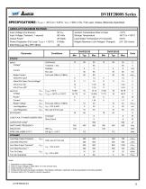
DVHF2800S SeriesSPECIFICATIONS (Tcase = -55°C to +125°C, Vin = +28V ± 5%, Full Load, Unless Otherwise Specified) ABSOLUTE MAXIMUM RATINGS Notes: 1. Dependent on output voltage. 2. Time for output voltage to settle within 1% of its nominal value. 3. Derate linearly to 0 at 135°C. 4. Verified by initial electrical design verification. Post design verification, parameter shall be guaranteed to the limits specified. 5. Correction factor of 0.12 added to ceramic capacitors.
Katalog auf Seite 5 öffnen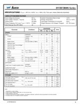
DVHF2800S SeriesSPECIFICATIONS (Tcase = -55°C to +125°C, Vin = +28V ± 5%, Full Load, Unless Otherwise Specified) ABSOLUTE MAXIMUM RATINGS Notes: 1. Dependent on output voltage. 2. Time for output voltage to settle within 1% of its nominal value. 3. Derate linearly to 0 at 135°C. 4. Verified by initial electrical design verification. Post design verification, parameter shall be guaranteed to the limits specified. 5. Correction factor of 0.12 added to ceramic capacitors.
Katalog auf Seite 6 öffnen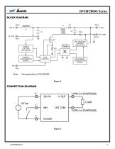
DVHF2800S Series BLOCK DIAGRAM PIN 8 UNDER VOLTAGE SHUTDOWN VOLTAGE AND CURRENT AMPLIFIERS PRIMARY HOUSEKEEPING SUPPLY SECONDARY HOUSEKEEPING SUPPLY CONNECTION DIAGRAM
Katalog auf Seite 7 öffnen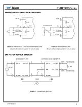
DVHF2800S Series INHIBIT DRIVE CONNECTION DIAGRAMS OPTIONAL CAPACITOR OPTIONAL CAPACITOR Figure 4 – Internal Inhibit Circuit and Recommended Drive Figure 5 – Isolated Inhibit Drive (Shown with optional capacitor for turn-on delay) (Shown with optional capacitor for turn-on delay) EMI FILTER HOOKUP DIAGRAM DVMH28 EMI FILTER 1 Figure 6 – Converter with EMI Filter
Katalog auf Seite 8 öffnen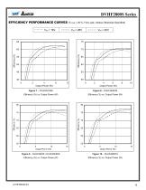
DVHF2800S Series EFFICIENCY PERFORMANCE CURVES (TCASE = 25°C, Full Load, Unless Otherwise Specified) VIN = 16V Efficiency (%) vs. Output Power (W) Efficiency (%) vs. Output Power (W) Efficiency (%) vs. Output Power (W) Efficiency (%) vs. Output Power (W)
Katalog auf Seite 9 öffnen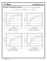
DVHF2800S Series EFFICIENCY PERFORMANCE CURVES (TCASE = 25°C, Full Load, Unless Otherwise Specified) VIN = 16V Efficiency (%) vs. Output Power (W) Efficiency (%) vs. Output Power (W) Efficiency (%) vs. Output Power (W) Efficiency (%) vs. Output Power (W)
Katalog auf Seite 10 öffnen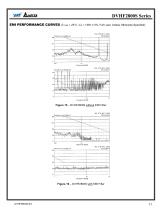
DVHF2800S Series EMI PERFORMANCE CURVES (TCASE = 25°C, VIN = +28V ± 5%, Full Load, Unless Otherwise Specified) Figure 15 – DVHF2800S without EMI Filter Figure 16 – DVHF2800S with EMI Filter
Katalog auf Seite 11 öffnen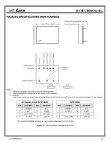
Dimensional limits are ±0.005” unless otherwise specified. Case temperature is measured on the center of the baseplate. Material: Case (Steel, Gold over Nickel Plated), Cover (Steel, Nickel Plated), Pins (Alloy 52, Gold over Nickel Plated), Pin Seal (Glass). *Pin 3 of DVHF2828S provides a +14V output referenced to OUT COM. Figure 17 - Non-Flanged Package and Pinout
Katalog auf Seite 12 öffnenAlle Kataloge und technischen Broschüren von VPT INC.
-
 DVETR2800S
16 Seiten
-
 DVEHF2800T
12 Seiten
-
 DVPL0510S
13 Seiten
-
 DVPL0505S
13 Seiten
-
 DVPL0503S
12 Seiten
-
 DVMSA28
9 Seiten
-
 DVFL2800D
28 Seiten
-
 DVFL2800S
30 Seiten
-
 DVHE2800S
15 Seiten
-
 DVTR2800D
21 Seiten
-
 DVTR2800S
22 Seiten
-
 DVTR2800T
15 Seiten
-
 DVWR2800T
14 Seiten
-
 DVHF2800D
17 Seiten
-
 DVAB2800D
14 Seiten
-
 DVHF+2800T
17 Seiten
-
 DVHV2800D
17 Seiten
-
 DVSB2800D
14 Seiten
-
 DVHV2800S
17 Seiten
-
 DVGF+2800T
15 Seiten
-
 DVSA2800D
16 Seiten
-
 DVSA2800S
15 Seiten
-
 DVCH2800S
14 Seiten