
Katalogauszüge

Fire Prevention Part V – 4/2007 Differential pressure systems Smoke and heat control of escape routes in accordance with DIN EN 12101-6
Katalog auf Seite 1 öffnen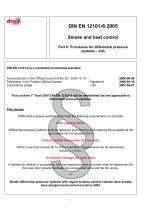
DIN EN 12101-6:2005 Smoke and heat control Part 6: Provisions for differential pressure systems – kits DIN EN 12101-6 is a mandated harmonized standard. Announcement in the Official Journal of the EC: 2005-12-14 / Publication in the Federal Official Gazette / Gazette of Coexistence phase until Thus as from 1st April 2007 DIN EN 12101-6 will be established law and applicable to differential pressure systems. This means: Differential pressure systems shall meet the following requirements on principle: Door opening force: Differential pressure systems shall be designed such that the door...
Katalog auf Seite 2 öffnen
The term "kit": stabilized axial-flow fan and control valve Opening moment Closing moment
Katalog auf Seite 3 öffnen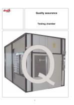
Quality assurance Testing chamber
Katalog auf Seite 4 öffnen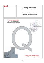
Quality assurance Control valve systems 10.000 cycles loading of all mechanical parts, afterwards functional testing Twelve-month weather testing of all mechanical parts 4
Katalog auf Seite 5 öffnen
Quality assurance System safety EKS-D control Line Smoke control exhaust device smoke detector and manual alarm box control damper (SLC) monitored oke control press monitored Multi-blade damp monitored Building control technology contacts monitored monitored Fire alarm system
Katalog auf Seite 6 öffnen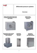
Differential pressure systems Smoke control pressure device with an integral automatical control valve Type: DV-RK1 Discharge fan with an integral automatical control valve Type: DV-RK2-EV Smoke control pressure device Type: DV1 Automatical control valve Type: RK2 Automatical discharge unit Type: RK2-JZI-DS-AH
Katalog auf Seite 7 öffnen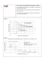
The permissible pressure difference Ap in Pa (diagram 1) is determined by the appropriate door surface. The pressure difference supplies the energy for the flow through the open The achieved velocity does not allow smoke to flow into the staircase at certain temperatures (diagram 2). Velocity through the door in m/s
Katalog auf Seite 8 öffnen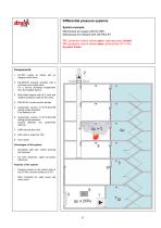
Differential pressure systems System example: Mechanical air supply with DV-RK1 Mechanical air exhaust with DS-RK2-EV RK1 pressure control valves open, staircase door closed RK2 pressure control valves open, exhaust fan DV in the by-pass mode Components: 1. DV-RK1 supply air device with an integral control valve 2. DS-RK2-EV exhaust ventilator with a roof base and control valve. For a secure discharge independent from the weather factors. 3. Multi-blade damper with SLC drive and weather protection grille for the wake 4. RKI-90 SLC smoke control damper 5. Appropriate number of ST-P-DA-STB...
Katalog auf Seite 9 öffnen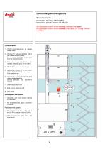
Differential pressure systems System example: Mechanical air supply with DV-RK1 Mechanical air exhaust with DS-RK2-EV RK1 pressure control valves closed, staircase door open RK2 pressure control valves closed, exhaust fan DV during nominal operation Components: 1. DV-RK1 box device with an integral control valve 2. DS-RK2-EV exhaust ventilator with a roof base and control valve. For a secure discharge independent from the weather factors. 3. Multi-blade damper with SLC drive and weather protection grille for the wake 4. RKI-90 SLC smoke control damper 5. Appropriate number of ST-P-DA-STB...
Katalog auf Seite 10 öffnen
Differential pressure systems System example: Mechanical air supply with DV1 RK2-JZI-DS-AH discharge unit with pressure control valve Natural discharge in the fire level RK2 pressure control valves open, staircase door closed Facade discharge area open Components: 1. DV1 supply air fan as a box device 2. Pressure relief unit with integral RK2 control valve and powered JZI (SLC) multi-blade damper 3. Multi-blade damper (SLC drive) with a weather protection grille for the wake 4. Appropriate number of ST-P-DA-STB ceiling smoke detectors First detection row 5. Appropriate number of ST-P-DA-STB...
Katalog auf Seite 11 öffnen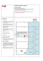
Differential pressure systems System example: Mechanical air supply with DV1 RK2-JZI-DS-AH discharge unit with pressure control valve Natural discharge in the fire level RK2 pressure control valves closed, staircase door and facade discharge area open Components: 1. DV1 box device 2. Pressure relief unit with integral RK2 control valve and powered JZI (SLC) multi-blade damper 3. Multi-blade damper (SLC drive) with a weather protection grille for the wake 4. Appropriate number of ST-P-DA-STB ceiling smoke detectors First detection row 5. Appropriate number of ST-P-DA-STB ceiling smoke...
Katalog auf Seite 12 öffnen
Differential pressure systems System example: Mechanical air supply with DV1 RK2-JZI-DS-AH discharge unit with pressure control valve Overflow between floodgate and elevator lobby, all floors with the same preference regarding the flow-through RK2 pressure control valve open, staircase doors closed and facade discharge area open Discharge elevator shaft These areas determine the leakage flow rate 2. Pressure relief unit with integral RK2 control valve and powered JZI (SLC) multi-blade damper 3. Multi-blade damper (SLC drive) with a weather protection grille for the wake 4. Appropriate...
Katalog auf Seite 13 öffnen
Differential pressure systems System example: Mechanical air supply with DV1 RK2-JZI-DS-AH discharge unit with pressure control valve Overflow between floodgate and elevator lobby, all floor with the same preference regarding the flow-through RK2 pressure control valve closed, staircase doors closed and fire room door as well as facade discharge area open Discharge elevator shaft These areas determine the leakage flow rate 2. Pressure relief unit with integral RK2 control valve and powered JZI (SLC) multi-blade damper 3. Multi-blade damper (SLC drive) with a weather protection grille for...
Katalog auf Seite 14 öffnen
DV1 – supply air fan as a box device Accessories: 1. Protection grille: at the suction side or at the pressure side 2. Elastic spigot: at the suction side or at the pressure side 3. Multi-blade damper with a SFR 1.90SLC drive – affixed at the pressure side 4. Repair switch in the direction of flow – affixed at the top, at the side (on the left/right side) * Rubber vibration damper included in the scope of delivery Main dimensions (mm) Type
Katalog auf Seite 15 öffnen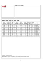
Arrangement: Fan blowing out freely The above table lists a selection of operating points. Further operating points are achievable on request.
Katalog auf Seite 16 öffnenAlle Kataloge und technischen Broschüren von Strulik GmbH
-
 Ventilatoren für AIROSET-System
16 Seiten
-
 BEK
BEK15 Seiten
-
 BCF-K90
16 Seiten
-
 BCF-2-K90
19 Seiten
-
 Fire Prevention Part III
82 Seiten
-
 Fire Prevention Part II
61 Seiten
-
 Fire Prevention Part I
213 Seiten