Katalogauszüge
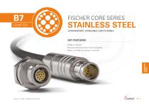
FISCHER CORE SERIES STAINLESS STEEL ULTRA-RESISTANT | STERILIZABLE | EASY TO HANDLE KEY FEATURES IP68 or hermetic Nuclear decontamination fluids compatible STAINLESS STEEL Easy to handle with gloves or remotely Version 4.1 − 08.2024 − Changes without prior notice
Katalog auf Seite 1 öffnen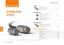
STAINLESS STEEL FEEDTHROUGH PANEL FRONT MOUNTED STAINLESS STEEL Technical Specifications
Katalog auf Seite 2 öffnen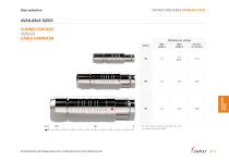
Size selection FISCHER CORE SERIES STAINLESS STEEL AVAILABLE SIZES CONNECTOR SIZE VERSUS CABLE DIAMETER All dimensions and images shown are in millimeters and are for reference only. STAINLESS STEEL Multipole low voltage Min cable ø For max cable ø, values in parenthesis are valid for sealed connectors (IP68).
Katalog auf Seite 3 öffnen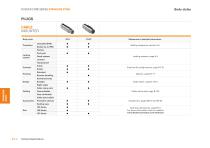
Body styles FISCHER CORE SERIES STAINLESS STEEL PLUGS CABLE MOUNTED Body style Protection References to detailed information Sealing categories, section A-6 Friction Locking system Push-pull Quick-release Locking systems, page A-5 Lanyard Tamperproof Contacts Housing Crimp Solder Standard Remote handling Electrical & configurations, page B 7-10 Options, page B 7-17 Shortened body Design Body styles, chapter B7-4 STAINLESS STEEL Cable clamp sets Cabling Cable clamp sets, page B 7-20 Heat shrinkable Cable bend reliefs Accessories Protective sleeves Sealing caps 103 Series Size Technical...
Katalog auf Seite 4 öffnen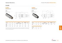
Technical dimensions FISCHER CORE SERIES STAINLESS STEEL PLUGS CABLE MOUNTED CABLE MOUNTED BODY STYLE BODY STYLE Torque [Nm] are recommended values that may be influenced by the characteristics of the cable jacket. Tests must be conducted to evaluate the exact values. To secure the cable clamp nut, we recommend the use of thread locking adhesive. All dimensions and images shown are in millimeters and are for reference only. STAINLESS STEEL
Katalog auf Seite 5 öffnen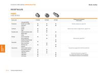
Body styles FISCHER CORE SERIES STAINLESS STEEL RECEPTACLES PANEL MOUNTED Body style References to detailed information Sealing categories, page A-6 Hermetic Crimp Contacts Electrical & contact configurations, page B 7-10 Natural stainless steel Right-angle Flush Front-projecting Rear-projecting Body styles, page B7-6 Bulkhead feedthrough Assembly Front-mounting Rear-mounting STAINLESS STEEL Sealing caps Spacers Accessories Color-coded washers Grounding washers Locking washers 103 Series 105 Series 107 Series Technical Specifications Technical dimensions, page B 7-7 For more information...
Katalog auf Seite 6 öffnen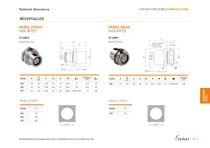
Technical dimensions FISCHER CORE SERIES STAINLESS STEEL RECEPTACLES PANEL FRONT MOUNTED PANEL REAR MOUNTED BODY STYLE BODY STYLE with or without ground tag or ground pin PANEL CUT-OUT Series PANEL CUT-OUT Series STAINLESS STEEL All dimensions and images shown are in millimeters and are for reference only.
Katalog auf Seite 7 öffnen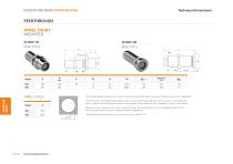
Technical dimensions FISCHER CORE SERIES STAINLESS STEEL FEEDTHROUGH PANEL FRONT MOUNTED ST-WDE 103 BODY STYLE BODY STYLE STAINLESS STEEL PANEL CUT-OUT Series Technical Specifications The "AZ" version of the feedthrough accepts a type "A" plug on the flange side and a type "Z" plug on the threaded end, which is typically oriented toward the interior of the chassis. In the version "ZA" the connections "A" and "Z" are inverted. Dimension "B max" specifies the maximum panel thickness. For panels thinner than the unthreaded section "E min", we can provide spacers as shown accessories section,...
Katalog auf Seite 8 öffnen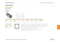
Technical dimensions FISCHER CORE SERIES STAINLESS STEEL FEEDTHROUGH PANEL FRONT MOUNTED ST-WDE 107 BODY STYLE PANEL CUT-OUT Series 107 The bulkhead feedthrough connector allows the passing of electrical signals and power through a panel via two cable plugs. The "AZ" version of the feedthrough accepts a type "A" plug on the flange side and a type "Z" plug on the threaded end, which is typically oriented toward the interior of the chassis. In the version "ZA" the connections "A" and "Z" are inverted. STAINLESS STEEL Dimension "B max" specifies the maximum panel thickness. For panels thinner...
Katalog auf Seite 9 öffnen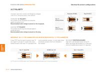
Electrical & contact configurations FISCHER CORE SERIES STAINLESS STEEL A/Z POLARITY Receptacle ST-DBEE To protect users from contact with dangerous voltages, most of our connectors exist in two versions: STANDARD "A" POLARITY The contacts of the receptacle are protected against accidental touch. Recommended when voltage is present on the receptacle. INVERTED "Z" POLARITY The contacts of the plug are protected against accidental touch. Recommended when voltage is present on the plug. Plug ST-S/ST-ST Type "A" Standard Polarity Type "Z" Inverted Polarity IMPORTANT : AN "A" TYPE CONNECTOR CAN...
Katalog auf Seite 10 öffnen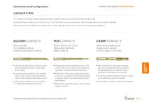
Electrical & contact configurations FISCHER CORE SERIES STAINLESS STEEL CONTACT TYPES The Fischer Connectors’ contact designs are highly reliable and are guaranteed up to 5,000 mating cycles. All standard brass and bronze contacts for use in the Core Series are screw machined, and all are gold plated over a nickel underplate. SOLDER CONTACTS CRIMP CONTACTS Most versatile Pre-installed contacts Qualified assemblers required PCB or Flex circuit mount Reduced pin diameter Wave soldering Selectively annealed area Special tools required Limited range of wire sizes Can be produced with any type...
Katalog auf Seite 11 öffnen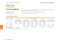
Electrical & contact configurations FISCHER CORE SERIES STAINLESS STEEL CONTACT TYPES CRIMP CONTACTS Each contact has a selectively annealed area which is crushed during assembly by specialized tooling to ensure proper termination of the wire to the contact. Selectively annealed area Special tools required Limited range of wire sizes Commonly used for field termination or repair, as no soldering is required. Not available for sealed or hermetic connectors. TOOLING FOR CRIMP CONTACTS Series STAINLESS STEEL Part number Part number Part number Part number Part number Crimp tool part number See...
Katalog auf Seite 12 öffnen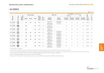
Electrical & contact configurations FISCHER CORE SERIES STAINLESS STEEL 103 SERIES = Standard Test voltage [kV] in mated position Crimp contacts STAINLESS STEEL Wire size 2) Contact ø [mm] Contact types Insulating material Stranding values are in brackets. For a given AWG, the diameter of some stranded conductor designs could exceptionally be larger than the hole diameter of the barrel. Testing may be required. Current per contact at 40°C temperature rise measured on the basic curve according to IEC 60512-5-2-5b. For the max. operating current a reduction factor must be used and limitations...
Katalog auf Seite 13 öffnenAlle Kataloge und technischen Broschüren von Fischer Connectors
-
 Fischer Core Series Brass
178 Seiten
-
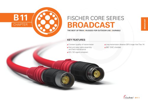 Fischer Core Series Broadcast
29 Seiten
-
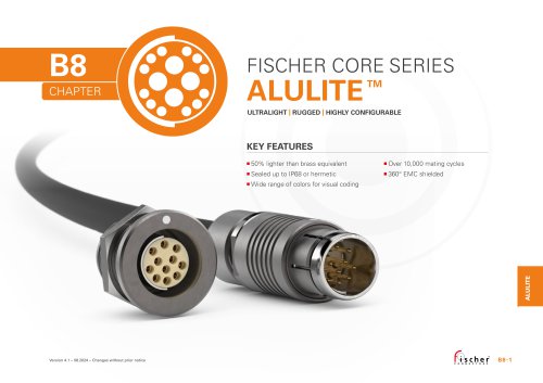 Fischer Core Series Alulite™
32 Seiten
-
 Connectors Overview
2 Seiten
-
 Cable Assembly Solutions
4 Seiten
-
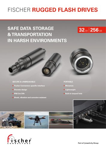 Fischer Rugged Flash Drives
4 Seiten
-
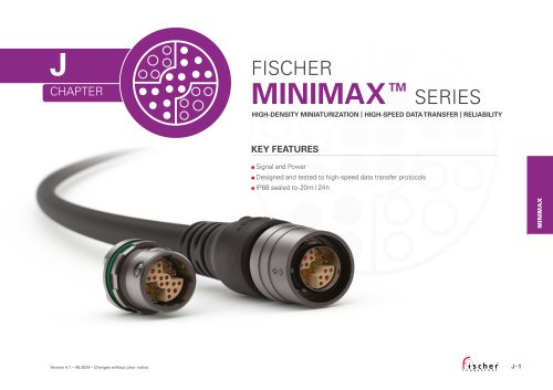 Fischer MiniMax™ Series
27 Seiten
-
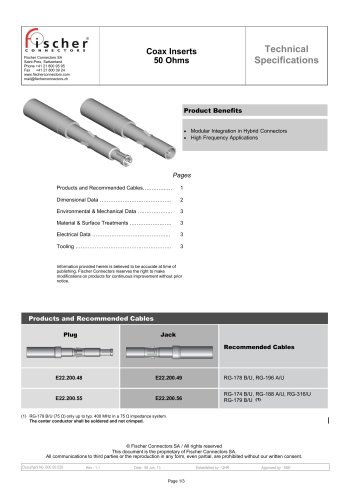 Coax Inserts 50 Ohms
3 Seiten
-
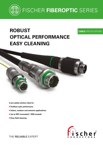
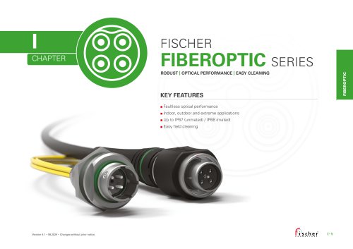 Fischer FiberOptic Series
32 Seiten
-
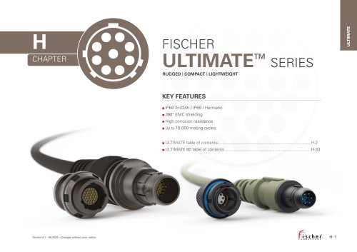 Fischer UltiMate™ Series
45 Seiten
-
 Technical Specifications Volume 2
148 Seiten
-
 Technical Specifications Volume 1
293 Seiten